
Official Arduino MKR Vidor 4000 ABX00022
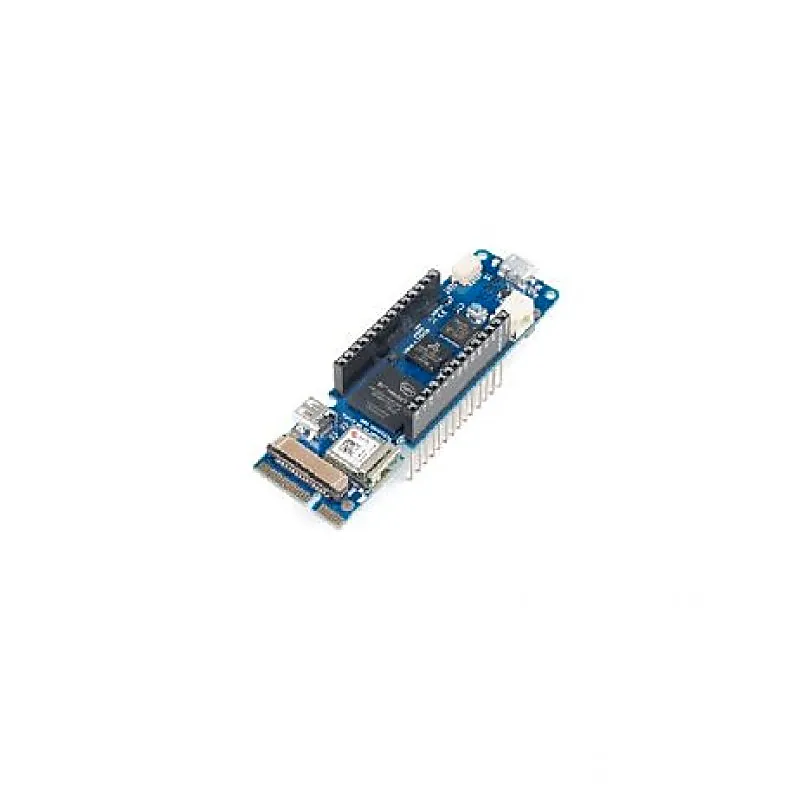
Official Arduino MKR Vidor 4000 ABX00022
The Official Arduino MKR Vidor 4000 brings Arduinos ease of use to the work with the most powerful reprogrammable chips that exist: FPGAs. With Vidor, you can create a board where all pins are PWM signals controlling the speed of motors. You can capture sound in real-time and make a sound effect ped
+ 18% GST (added at checkout)
In stock — 3 units ready
- Open the Official Arduino IDE. Go to Tools->Boards->Boards Manager. Search and install Official Arduino SAMD boards.
- Go to Tools->Manage Libraries. Search and install WiFiNINA ver. 1.3.0 library.
- Go to File->Examples->WiFiNINA->Scan Networks. Select correct COM port. Compile and upload the program. Check the output in Serial Monitor.
- All pins are PWM pins
- MIPI camera connector
- Mini PCI Express port with programmable pins
- Full-Speed USB Device and embedded Host
- FPGA: Intel Cyclone 10CL016
- PCI: Mini PCI Express port with programmable pins
- Camera Connector: MIPI camera connector
- Circuit Operating Voltage: 3.3V
- Digital I/O Pins: 22 headers + 25 Mini PCI Express
- PWM Pins: All Pins
- UART: Up to 7 (depends on FPGA configuration)
- SPI: Up to 7 (depends on FPGA configuration)
- I2C: Up to 7 (depends on FPGA configuration)
- Analog Input Pins: n/a
- Analog Output Pins: n/a
- External Interrupts: n/a
- DC Current per I/O Pin:4 or 8 mA
- Flash Memory:2 MB
- SDRAM: 8 MB
- EEPROM:n/a
- Clock Speed:48 MHz up to 200 MHz
- Video Output: Micro HDMI
Buying in bulk?
Get volume pricing, GST invoicing and stock availability for larger quantities of this item.
The Official Arduino MKR Vidor 4000 brings Arduinos ease of use to the work with the most powerful reprogrammable chips that exist: FPGAs. With Vidor, you can create a board where all pins are PWM signals controlling the speed of motors. You can capture sound in real-time and make a sound effect pedal for your guitar. It is possible to create a real-time computer reading sensor information and sending it to a state-of-the-art monitor or capture video and overlay sensor information on the image that will then later be sent over to a screen. You can connect to the Official Arduino IoT Cloud and control a complex laboratory machine running a large number of motors. You could even prototype your own processors inside the FPGA and have them work in parallel to the other microcontroller on the board. Vidor is a device that invites experimentation, precision, and high-speed computation. The board comes with 8 MB of SRAM to support the FPGA operations on video and audio. The FPGA code is stored in a 2 MB QSPI Flash chip, of which 1 MB is allocated for user applications. It is possible to perform high-speed DSP operations for audio and video processing. Therefore, the Vidor includes a Micro HDMI connector for audio and video output and a MIPI camera connector for video input. All of the boards pins are driven both by SAMD21 and FPGA while respecting the MKR family format. Useful Steps: Open the Official Arduino IDE. Go to Tools->Boards->Boards Manager. Search and install Official Arduino SAMD boards. Go to Tools->Manage Libraries. Search and install WiFiNINA ver. 1.3.0 library. Go to File->Examples->WiFiNINA->Scan Networks. Select correct COM port. Compile and upload the program. Check the output in Serial Monitor. Use your MKR board on Arduinos IoT Cloud, a simple and fast way to ensure secure communication for all of your connected Things. Features: All pins are PWM pins MIPI camera connector Mini PCI Express port with programmable pins Full-Speed USB Device and embedded Host FPGA Block Specifications: FPGA: Intel Cyclone 10CL016 PCI: Mini PCI Express port with programmable pins Camera Connector: MIPI camera connector Circuit Operating Voltage: 3.3V Digital I/O Pins: 22 headers + 25 Mini PCI Express PWM Pins: All Pins UART: Up to 7 (depends on FPGA configuration) SPI: Up to 7 (depends on FPGA configuration) I2C: Up to 7 (depends on FPGA configuration) Analog Input Pins: n/a Analog Output Pins: n/a External Interrupts: n/a DC Current per I/O Pin:4 or 8 mA Flash Memory:2 MB SDRAM: 8 MB EEPROM:n/a Clock Speed:48 MHz up to 200 MHz Video Output: Micro HDMI Package Includes: 1 x Official Arduino MKR Vidor 4000 ABX00022 Attachments : Download Download Download
You may also need
Official Arduino MKR Vidor 4000 ABX00022